About Me
Hello! I'm Steven Rodriguez, a Mechanical Engineering student at Florida International University with a passion for rapid prototyping, test engineering, embedded software, network programming, and offensive security.My professional and academic journey as well as my own self teaching have provided me with a strong background in Design for Manufacturing paired with solid understanding and experience in microprocessors, microcontrollers, and computer architecture as well as TCP/IP, data structures and algorithms (DSA), object-oriented programming (OOP) in C/C++ & Python, and serial communication protocols ( I2C, UART, SPI, etc. ).I’m eager to apply my background, experience, and knowledge to solve real world problems and create a lasting positive impact in the world.
Featured Projects
Mechanical Engineering
Learn about my professional, academic, and personal project experience in mechanical engineering.


Software Engineering
Learn about my professional, academic, and personal project experience in software engineering.
Professional Experience
Blue Origin
Test Fixture Designs
May 2024 - August 2024
Creo Parametric for designing and creation of test fixture GD&T drawings as well as test order.

Sabrewing Aircraft
UAV Nacelle Optimization
June 2023 - August 2023
Fusion 360 for UAV nacelle refinement and critical feature preservation. Rapid prototyping techniques and future aircraft manufacturing integration.

Undergraduate Research
FIU Applied Research Center
Vector Fan Optimization
February 2023 - April 2023
Used SolidWorks and ANSYS to improve design, enhance aerodynamics, and reduce thrust loss of vector fan.

Welding Gun Optimization
November 2022 - February 2023
Designed a precision mount using SolidWorks to ensure optimal alignment between the welding gun tip and the tool center point for accurate ROS simulations.
Clubs & Organizations
Manufacturing Processes
Card holder, spin top, & Injection mold
Spring 2024 & Fall 2024
Created a card holder, a spinning top, and an injection mold using different manufacturing processes.

FIU Panther aero
Pantha Ray Aircraft
July 2022 - December 2022
Conducted weekly meetings to teach team members how to use SolidWorks, ANSYS, and MATLAB.

FIU Eco Engineering
Car Shell Design
August 2022 - December 2022
Conceptualized, designed, and tested three aerodynamic shells using Fusion 360.

Professional Experience
Blue Origin
Software Verification Tool
May 2024 - August 2024
Tool feature addition using CI/CD and software tool verification using test cases.

Hackathons
ShellHacks 2024
SmartChoices
September 2024 - September 2024
Created a financial literacy tool for high school kids 9-12 that could be used by teachers to challenge students in the classroom to learn about financial decisions.

Clubs & Organizations
INIT Build
Butterfly Garden Ai Monitoring System
October 2024 - Present
A collaborative project between INIT FIU and the Green Campus Initiative FIU aims to develop a monitoring system for a future butterfly garden.

Students for the Exploration and Development of Space ( SEDS )
Payload rover 2023
March 2023 - June 2023
Fully functional rover equipped with telemetry sensors, microcontroller, and computer all connected through a PCB which helped SEDS FIU place 26th out of 100+ teams at Spaceport America Cup 2023.

FIU Curriculum
FIU Navigation Map
January 2024 - Present
A senior capstone project with the aim of developing a navigation tool for the FIU Engineering Center.

Obstacle Avoidance Robot
January 2024 - May 2024
An obstacle avoiding robot that utilizes a state machine architecture using C/C++ and electronic hardware.
Personal Projects
6502 Computer from scratch
August 2024 - December 2024
Personal project with the aim of printing Hello World on a LCD screen through utilizing a 6502 microprocessor and additional supporting hardware.
Custom Test Fixtures for attenuation performance data
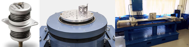
Test stand fixtures for vibration and pyroshock testing in three axes were designed using Creo, resulting in performance data on two isolators' attenuation, with assembly and machine part drawings created using GD&T per ASME Y14.5, along with work orders developed and submitted for test engineers to execute procedures.
Process Overview
Objective
To CAD design, create drawings, and create test orders for custom test fixtures, enabling the collection of attenuation performance data during pyroshock and vibration testing.
Tools and Technologies

Creo Parametric | Windchill | GD&T Y14.5
Design & Planning Phase
1.) Understanding full scope of project:
Understanding the bigger picture and the vision
Understanding of test stand dimensions ( T2000 & Pyroshock Beam )
Understanding of test article dimensions ( Isolators )
Understanding of ideal fixture dimensions for accurate testing
2.) Commence CAD Design:
Overcome CREO learning curve and learn CAD naming conventions
Review various datasheets for inserts, screws, and bolts to identify the optimal components for integrating with CAD models.
3.) Commence CAD Drawings:
Overcome CREO drawing learning curve and learn drawing naming conventions
Review and learn linear dimensioning and GD&T concepts to improve the accuracy and quality of technical drawings.
4.) Commence Work Orders:
Overcome JULES learning curve
Review standard test procedures for pyroshock and vibration testing, adjusting them to fit the specific project needs
Communicated with test engineers to address missing procedures or pending hardware, ensuring all requirements were met to sign off on the work order and obtain approval for scheduling testing
Implementation & Execution
Integrated inserts, screws, and bolts with their corresponding test fixtures to prepare for handing off to the test engineers
Testing & Validation
Assembled fixtures were handed off to test engineers in person, where uncertainties, doubts, and questions were addressed to ensure clarity and move forward with testing.
Result & Impact
Valuable data was collected on the test articles that were tested which would provide direction moving forward on what test article to continue testing and what article to discontinue.
UAV Nacelle Optimization
Enhancement of the aerodynamic performance of a UAV nacelle by refining its design and creation of a 3D model for the second prototype using CNC, additive manufacturing, and composite materials.
Process Overview
Objective
To enhance the aerodynamic performance of a initial prototype UAV nacelle by refining its outer and inner contour creating a balance between optimal shape design and preservation of critical design features.
Tools and Technologies

Fusion 360 | CNC | Additive Manufacturing | Composite Materials
Design & Planning Phase
1.) Understanding full scope of project:
Gained insight into the design intent of the initial nacelle by reviewing documentation.
Identified key design features to retain, anticipated contour shape, and expected performance outcomes.
Compiled a list of potential shapes and outlined execution strategies for modeling in CAD.
2.) Commence CAD Design:
Gained insight into the design intent of the initial nacelle by reviewing documentation.
Identified key design features to retain, anticipated contour shape, and expected performance outcomes.
Compiled a list of potential shapes and outlined execution strategies for modeling in CAD.
Testing & Validation
Conducted CFD analysis to quantify static and dynamic thrust output of the new nacelle.
Adjusted the CAD design to minimize drag based on analysis findings.
Implementation & Execution
Employed roughing and surfacing CNC techniques, along with additive manufacturing and composite materials, to create a 3D small-scale model of the second iteration prototype
Result & Impact
Achieved an 8.50% improvement in peak velocity through design optimization.
Developed a flexible system of adjustable parameters for easy customization of nacelle features, enabling adaptation to evolving dimensional requirements for future manufacturing processes and aircraft integration.
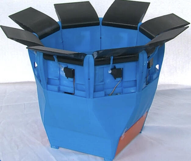
Vector Fan Optimization
Conducted tests on a wall crawler fan to evaluate air thrust output at varying angles, using SolidWorks and ANSYS to optimize the thrust vector design by improving material gaps and identifying areas of critical thrust loss for better aerodynamic performance.
Process Overview
Objective
To enhance the wall climber's ability to adhere to surfaces while leveraging thrust vector capabilities to support motor performance.
Tools and Technologies

SolidWorks | ANSYS
Planning Phase
Understanding full scope of project:
Get the bigger picture and goal of the project.
Gained insight into the design intent of the initial fan.
Identified key design features to retain, anticipated contour shape, and expected performance outcomes.
Initial Testing
Conducted comprehensive tests to evaluate the air thrust output of a thrust vector fan at various angles and air intensities to identify the angle associated with the greatest thrust loss.
Design Phase
Commence CAD Design:
Gained insight into the design intent of the initial nacelle by reviewing documentation.
Identified key design features to retain, anticipated contour shape, and expected performance outcomes.
Compiled a list of potential shapes and outlined execution strategies for modeling in CAD.
Implementation & Execution
Leveraged additive manufacturing to carry out design ideas
Result & Impact
Established a foundation for future users to continue the work by providing thorough documentation and conventionally named files.
UR-5 Welding Robot
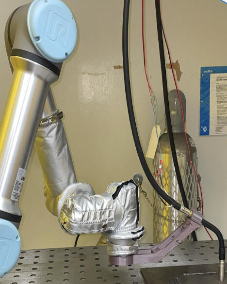
3D printed welding gun mount that was CAD designed to ensure optimal alignment of the welding gun tip with the tool center point for accurate performance in future ROS simulations.
Process Overview
Objective
To achieve optimal parallel alignment between the welding gun tip and the tool center point to ensure precise performance in future ROS simulations and further down the line accurate 3D weld manufacturing.
Tools and Technologies

SolidWorks
Design & Planning Phase
1.) Understanding full scope of project:
Developed an understanding of the ideal mount dimensions for accurate testing.
Obtained a UR-5 robot CAD model from online resources.
Acquired the initial CAD model of the mount prototype.
2.) Commence CAD Design:
Overcame the SOLIDWORKS learning curve to effectively utilize the software.
Designed a welding gun handle and gun compatible with the UR-5 model and the new mount design.
Created a new mount model based on specified parameters.
Testing & Validation
Provided PH.D student with CAD designs to use in ROS Simulations.
Adjust CAD model based on ROS simulation performance and results.
Implementation & Execution
Manufactured a precision welding gun mount using additive manufacturing, ensuring accurate fabrication according to design specifications.
Result & Impact
Achieved optimal parallel alignment between the welding gun tip and the tool center point.
Facilitated precise performance in future ROS simulations.
Facilitated accurate 3D weld manufacturing down the line.
Cardholder, spinning top, & injection mold
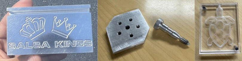
A course conducted during Spring and Fall 2024 focused on using MasterCAM for designing and generating G-Code to create a cardholder, spin top, and injection mold with a CNC mill and knee mill.
Process Overview
Objective
To develop proficiency in MasterCAM for designing and generating G-Code, enabling students to create precise components, such as a cardholder, spin top, and injection mold, using CNC and knee milling techniques, while emphasizing best practices in machining processes and equipment setup.
Tools and Technologies

MasterCAM | Knee Mill | CNC Mill | Lathe
Design & Planning Phase
Used MasterCAM for designing and generating G-Code
Machining & Manufacturing
Input G-Code into the CNC mill to efficiently remove large volumes of material and achieve precise design details.
Utilized the knee mill for accurate material removal, ensuring adherence to specified tolerances while performing spotting and pecking operations for hole creation.
Employed an automatic lathe to manufacture a bolt, including the creation of bolt threads and knurling on the bolt's top for enhanced grip.
Result & Impact
Card Holder with brand of my favorite salsa class studio.
Spin top composed of a top and bolt.
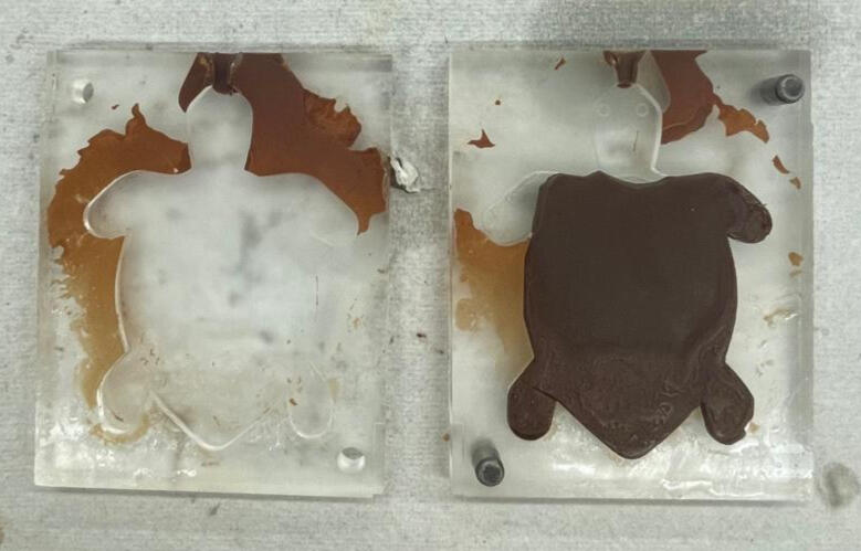
Injection mold for chocolate.
pantha ray aircraft
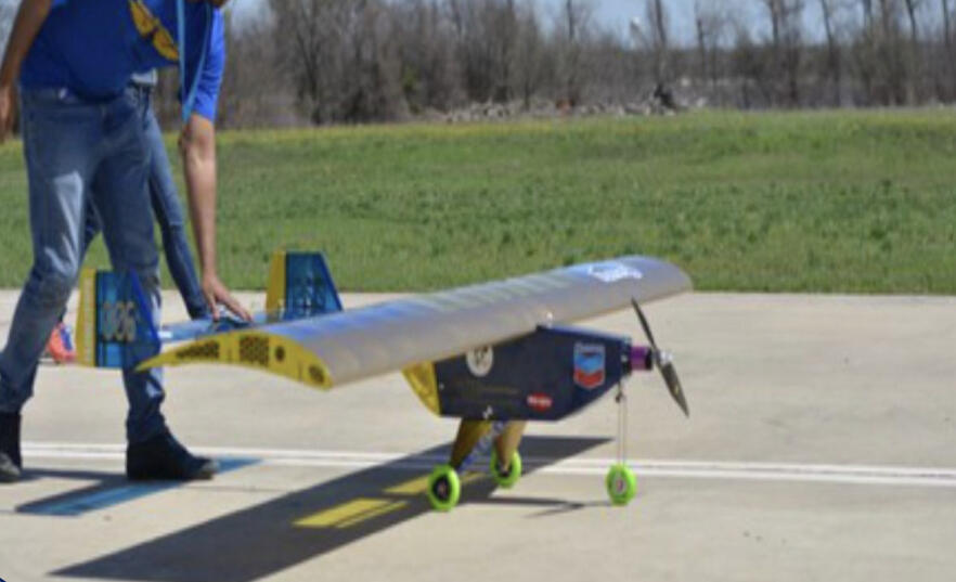
A project focused on selecting airfoil combinations using XFLR-5 to analyze aerodynamic characteristics, with weekly meetings to guide team members in using SolidWorks, ANSYS, and MATLAB for designing and optimizing a plane for short takeoffs.
Process Overview
Objective
To analyze various airfoil and their corresponding aerodynamic characteristics for the design, analysis, and optimization of an aircraft capable of taking off within 100 feet.
Tools and Technologies

SolidWorks | ANSYS | MATLAB | XFLR-5
Design & Planning Phase
1.) Airfoil Selection:
Utilized XFLR-5 to analyze different airfoils and their lift coefficient versus drag coefficient and angle of attack.
2.) Commence CAD Design:
Designed multiple Pantha-Ray models using the selected airfoil, each featuring differently extruded airfoils with varying winglet configurations.
Testing & Validation
Conducted Computational Fluid Dynamics (CFD) analysis on various Pantha-Ray models to visualize regions with significant drag.
Conducted Finite Element Analysis (FEA) on various Pantha-Ray models to evaluate their ability to withstand lift forces exerted during flight.
Implementation & Execution
Created CAD drawings for the manufacturing of the aircraft body.
Result & Impact
Secured 2nd place at the SAE Aero competition
windtunnel tests
Process Overview
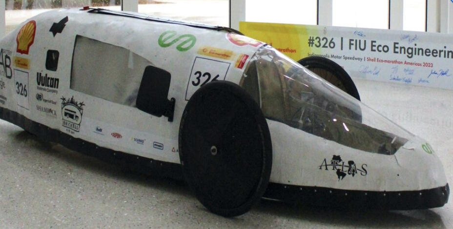
A project that involved conceptualizing and designing three aerodynamic shells using Fusion 360, reducing drag through ANSYS CFD analysis, and validating one design with 3D printing and wind tunnel testing.
Objective
To conceptualize, design, and test three aerodynamic shells using Fusion 360, employing ANSYS CFD analysis to reduce drag, and validating one design for improved aerodynamic performance.
Tools and Technologies

Fusion 360 | ANSYS
Design & Planning Phase
Commence CAD Design:
Designed three aerodynamic shells using Fusion 360.
Testing & Validation
Reduced drag through ANSYS CFD analysis.
Implementation & Execution
Validated one design using 3-D printing and wind tunnel testing.
Result & Impact
The validated design was manufactured for the shell to be implemented on the vehicle for the Shell Eco-Marathon.
Software Version Verification Tool
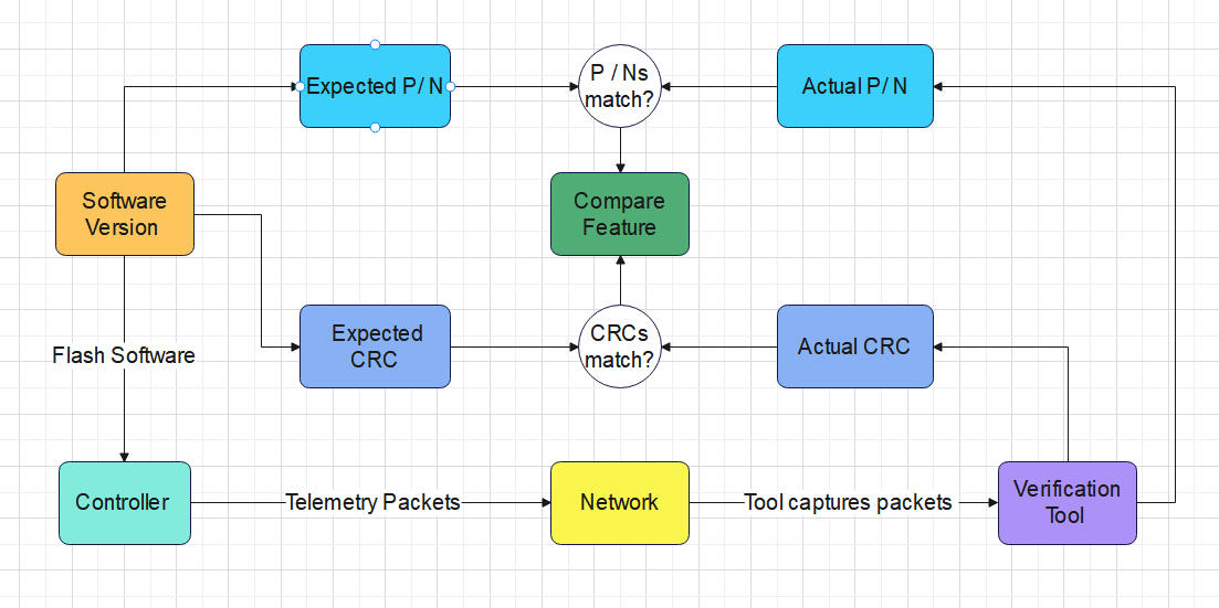
A project focused on implementing a tool feature in Python to enhance verification of software release components and flight controller telemetry.
Process Overview
Objective
To implement a feature in a software verification tool for comparing part numbers and CRCs and develop a command-line interface in Rust based on the existing Python tool.
Tools and Technologies

Python | Rust | Git | Gitlab | VS Code | Linux (Bash Shell )
Design & Planning Phase
1.) Understanding full scope of project:
Gained an understanding of the tool's usefulness and its potential impact.
Developed an understanding of software versions and DO-178C software categorization.
Reviewed existing code to understand its structure, identify key functions, and determine where to begin while clarifying the output of various components.
Testing & Validation
Verified the tool's feature functionality using Pytest by creating test cases that targeted edge scenarios, validated performance across different conditions, and ensured proper error handling.
Implementation & Execution
After successful testing and validation, the python tool feature was merged into the main branch.
The Rust command line feature was retained and moved to a separate branch for future enhancements.
Result & Impact
Tool would allow software engineers working with HILs to quickly verify proper software version flash.
Created a framework for transitioning a Python tool to Rust, enabling seamless future integration with mainframe systems.
SmartChoices
Smart Choices is an engaging educational game designed for high school students (grades 9-12) that teaches financial literacy and budgeting skills through real-life scenarios.
Process Overview
Objective
To create an financial literacy game targeting students grades 9-12 that can be leveraged by teachers to teach financial skills through real life scenarios.
Why?
Financial literacy education is lacking in K-12 programs across the country.
As part of the university ranked #1 in social mobility in the United States, the goal is to champion this ideal beyond the campus and into the broader community.
Create fun, engaging, and thought-provoking ways to teach financial literacy in a school setting.
High school students represent the most vulnerable group in making unwise financial decisions during the transition into adulthood, making them the target audience.
Tools and Technologies

Python | Streamlit | Git | Github
Design & Planning Phase
1.) Understanding full scope of project:
Discuss the tool features, necessary tools, realistic expectations for the two-day timeframe, and the vision behind the tool.
2.) Commence Development:
Utilized object-oriented programming principles to develop a structured system for managing player attributes, financial transactions, and tax calculations.
Created a front-end UI using Streamlit, integrating it with a Python backend.
Result & Impact
Login Credentials for Teacher: Access provided for game initiation and management.
Initiate a New Game: Option to start a new game or enter a previously started game.
Enter Number of Student Players: Input for up to 50 student players.
Assign Roles to Students: Each student receives a role that includes a job, income, and student.
Obstacle Avoidance Robot
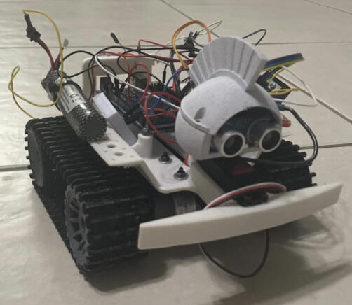
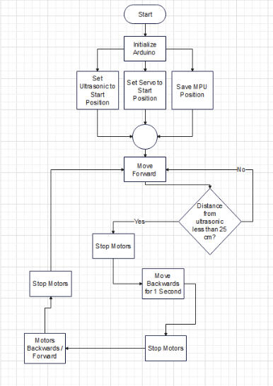
A robot designed for obstacle avoidance and autonomous navigation which utilizes real-time sensor data, it detects and responds to obstacles, ensuring smooth movement through its environment. A state machine manages various actions, including moving forward, backward, and turning, allowing for adaptive navigation.
Process Overview
Objective
To develop a robot that can navigate without colliding, stop and back up when encountering obstacles, scan for clear paths, and rotate towards free space to continue moving forward.
Tools and Technologies

C | C++ | Arduino IDE
Design & Planning Phase
1.) Understanding full scope of project:
Understand the assignment objective and outline achievable tasks within the given timeframe.
Create a detailed flowchart to illustrate the algorithm, outlining each step and decision point to provide a clear visual representation of the process.
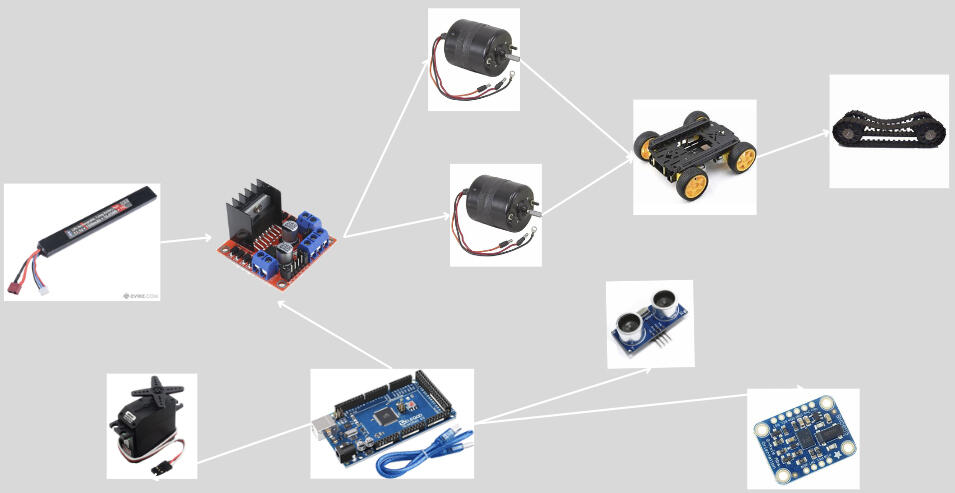
2.) Gather Hardware Components:
3.) Commence Assembling & Algorithm:
Overcame the SOLIDWORKS learning curve to effectively utilize the software.
Designed a welding gun handle and gun compatible with the UR-5 model and the new mount design.
Created a new mount model based on specified parameters.
Testing & Validation
Trial 1
The robot experienced delayed braking and a prolonged right turn.
Trial 2
Delayed braking has been fixed, but the robot still turns too far to the right.
Trial 3
Robot performed as intended.
Result & Impact
Implemented modular code for motor control and sensor integration to optimize performance and responsiveness, enhancing adaptability in dynamic environments.
Created an autonomous robot using a state machine architecture for real-time obstacle avoidance, incorporating ultrasonic and orientation sensors for smooth navigation.
Payload Rover 2023
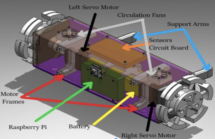
The SEDS Payload Rover was a rover that was deployed at Spaceport America Cup 2023 which was capable, upon establishment of power through a switch, of moving forward as well as collecting and storing telemetry data.
Process Overview
Objective
To develop a robot that can navigate without colliding, stop and back up when encountering obstacles, scan for clear paths, and rotate towards free space to continue moving forward.
Tools and Technologies

Python | C | C++ | Arduino IDE | VS Code | Linux ( Bash Shell )
Design & Planning Phase
1.) Understanding full scope of project:
Determine realistic objective and outline achievable tasks within the 3 month timeframe before competition.
Create a detailed flowchart to illustrating relationship between electronic components.
2.) Gather Hardware Components:
3.) Commence Assembling & Algorithm:
Designed a compact prototype PCB that integrated embedded systems and hardware components for a rover, featuring voltage regulation for improved electrical safety.
Utilized Git for collaborative development, troubleshooting, and extensive testing of C/C++ and Python code for embedded systems, managing various electronic hardware and mechanical components.
Testing & Validation
Component Testing
Validated functionality of individual electronic components.
System Testing
Validated functionality of entire system including prototype PCB.
Result & Impact
Developed modular code for efficient data collection using I2C and UART, contributing to a fully functional rover that helped the FIU team achieve 26th place out of over 100 teams at Spaceport America Cup 2023.
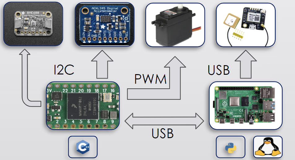
Butterfly Garden AI Monitoring System

A monitoring system for a future butterfly garden that FIU will implement in 2025, featuring a data display UI dashboard, occupancy count, and sensor data for fault detection and future data analysis to identify trends using machine learning.
Process Overview
Objective
To develop a monitoring system for a butterfly garden featuring mmWave motion detection, sensor data collection, and a database, incorporating machine learning for fault detection and future data analysis, along with a UI dashboard to display visitor data analytics.
Why?
This project, a collaboration between INIT FIU and the Green Campus Initiative, aims to enhance the management and conservation of the butterfly garden by combining technology for monitoring visitor interactions and environmental conditions with a love for sustainability.
Tools and Technologies

Python | Streamlit | Git | Github | VS Code | OpenCV
Design & Planning Phase
1.) Understanding full scope of project:
Outline the project's objective, essential requirements, and desirable enhancements.
Divided teams into Front-End, Hardware & Data, & Machine Learning Model.
2.) Commence Development:
Gather hardware components and program them to collect data.
Create a front-end UI using Streamlit, integrating it with a backend to display data.
Develop a machine learning model that can detect trends, patterns, or faults in the data.
Result & Impact
TBA
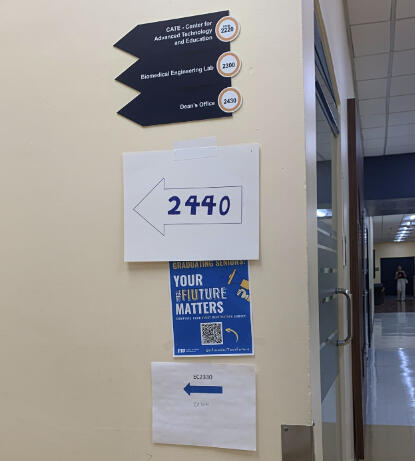
FIU Navigation Map
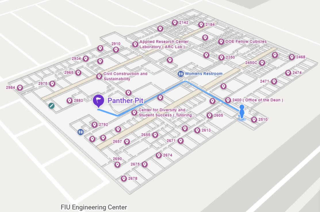
To address frequent navigation issues at the FIU Engineering Center, three interactive floor maps were created using Mappedin, with potential upgrades like multi-floor navigation, QR code integration, and customization to match FIU’s colors and fonts for improved accessibility.
Process Overview
Objective
Enhance navigation and user experience within the FIU Engineering Center by replacing outdated maps with a modern, interactive solution.
Why?
The complexity of the Engineering Center's layout, coupled with the diverse activities and resources housed within it, presented a significant need for an intuitive and efficient navigation solution.
Tools and Technologies
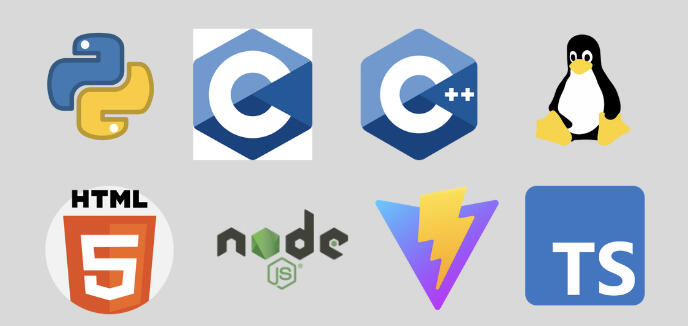
Python | C | C++ | Linux (Automation)
HTML | Node.js | Vite | Typescript
Design & Planning Phase
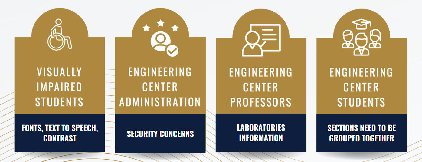
1.) Identify Stakeholders:
Key stakeholders were identified, the current state of the art was researched, and essential metrics were gathered to guide the evaluation process.
Through stakeholder analysis and in-depth interviews, pain points associated with existing navigation systems were uncovered, establishing a solid foundation for the project scope.
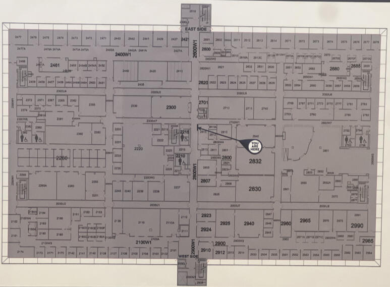
2.) Identify Current State of the Art:
Only basic floorplans, and don’t provide any features that would help the user with navigation.
3.) Core Metrics
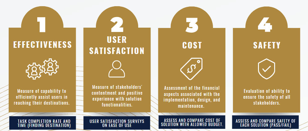
4.) Design Ideation:
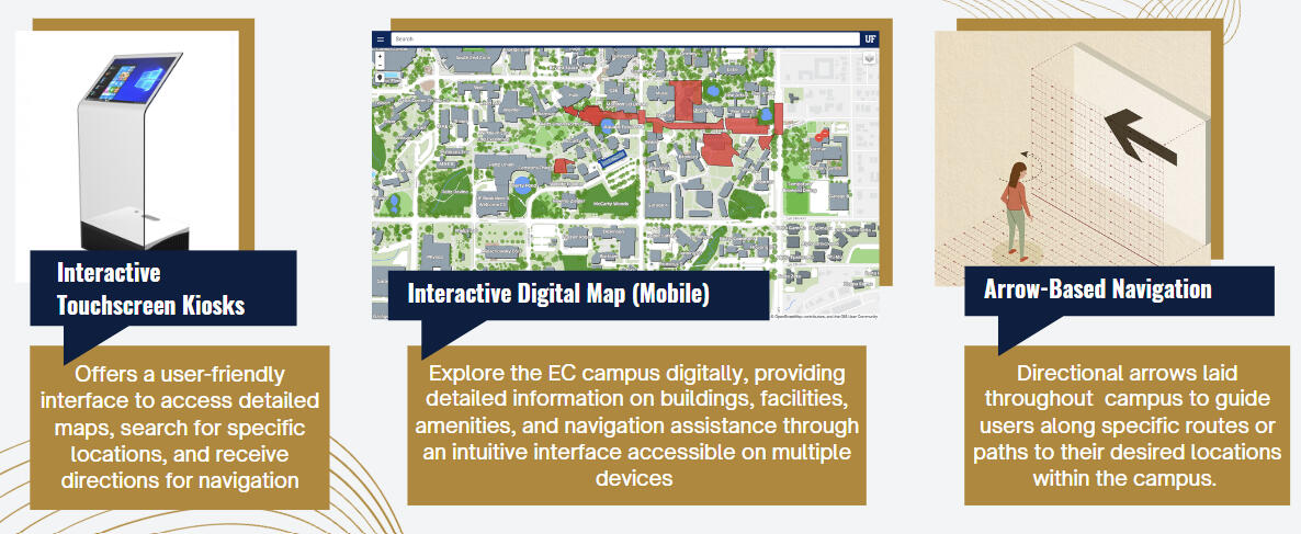
5.) Low Fidelity Testing:
Low-fidelity testing involves creating simplified, basic prototypes of a product or design to quickly gather feedback and evaluate concepts before investing in more detailed development.
Using the following methods to quantify and measure each low fidelity prototype performance, the best alternative was the Kiosk
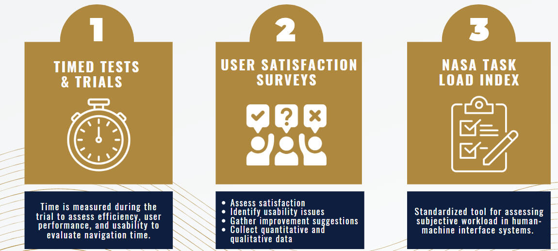
The best choice was the Kiosk.
Testing & Validation
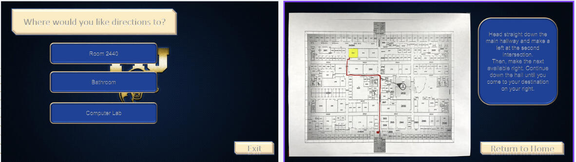
High Fidelity Prototype #1:
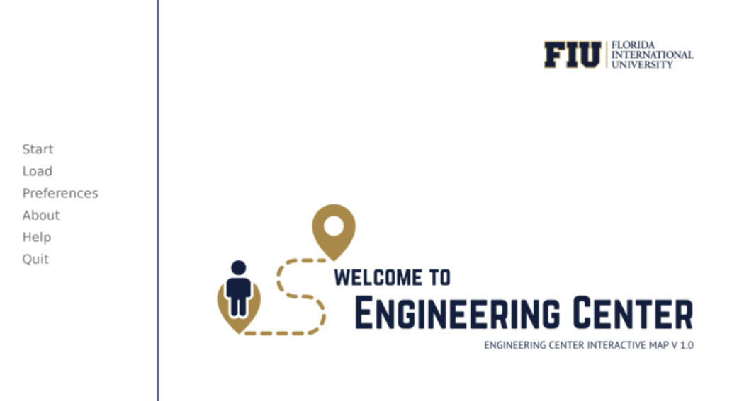
An initial high fidelity prototype User Interface was created using Runpy engine with button options that work upon clicking on them.
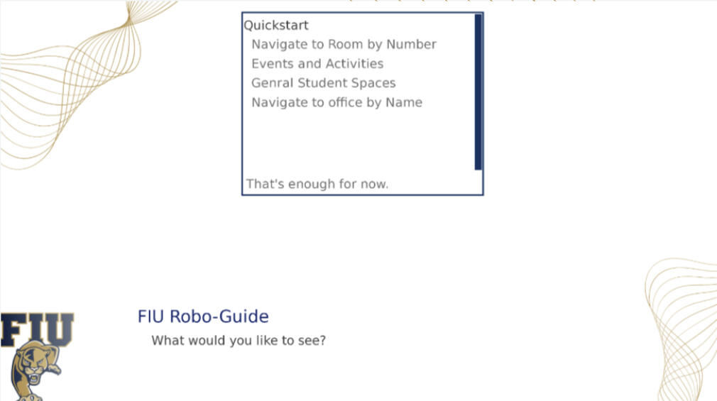
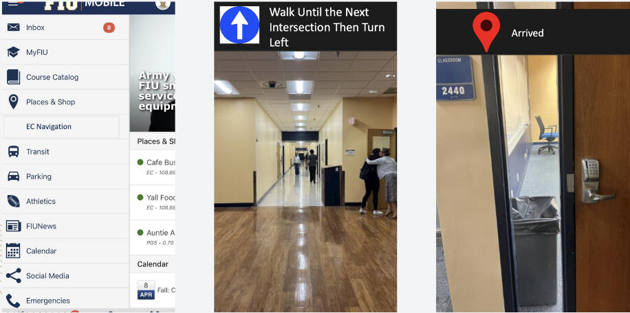
High Fidelity Prototype #2:
Based on user feedback on high fidelity #1, the UI was switched to being made with MappedIn to include:
Room Numbers
Reference Features
Quicker Options Menu
Implementation & Execution
Integrated the UI, Raspberry Pi, monitor, kiosk stand, and monitor casing to create a cohesive and functional kiosk system for secure access and information display.
Result & Impact
Improved navigation for FIU Engineering Center students and faculty by 70%, addressing key challenges identified through stakeholder feedback and analysis.
Developed a C++ barcode scanner repository with comprehensive documentation to support future contributions and enhance secure kiosk access exclusively for FIU students, faculty, and staff.
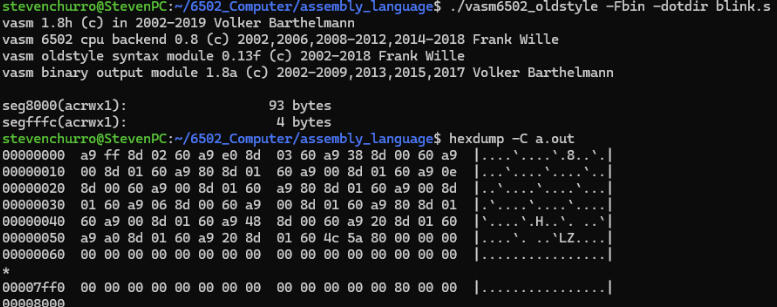
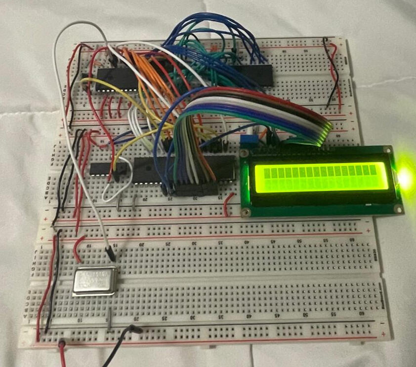
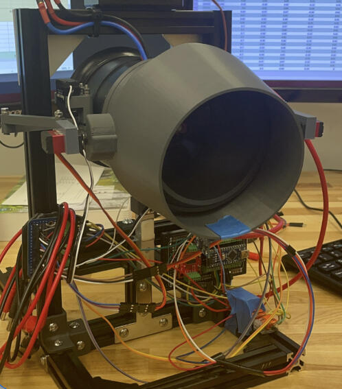
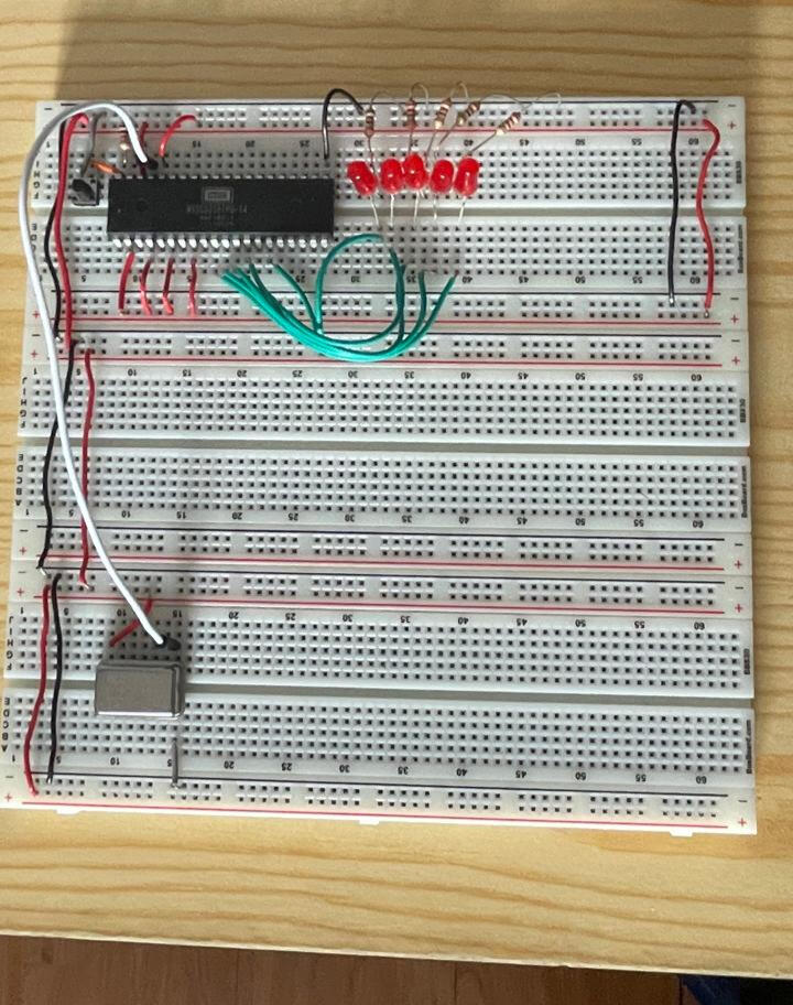
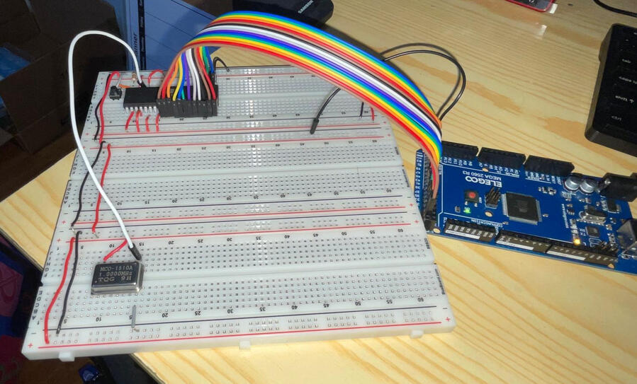
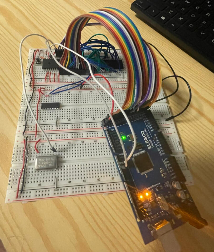
6502 Computer from scratch
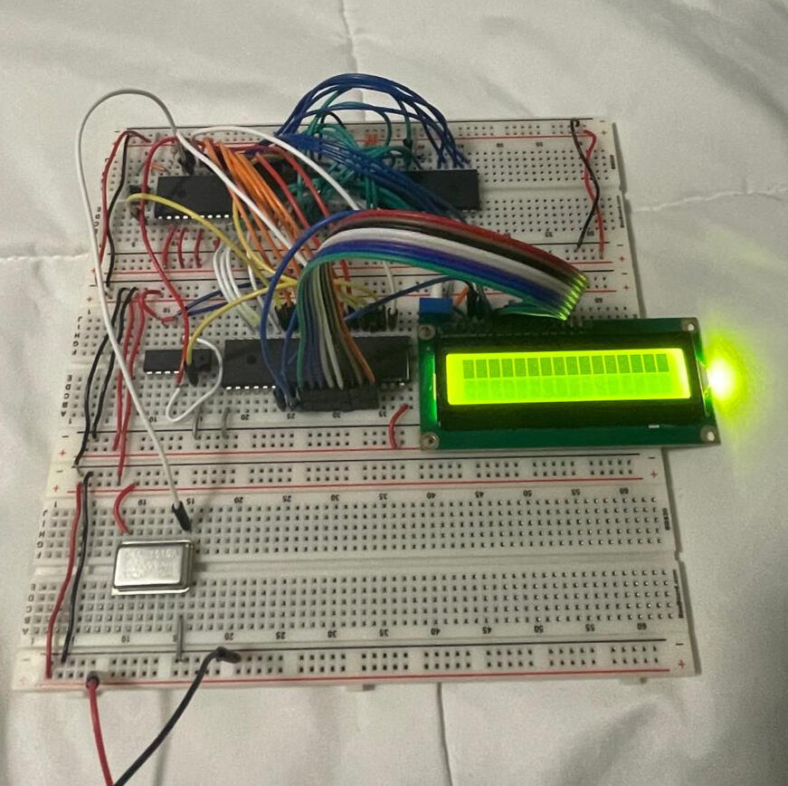
Developed and optimized a custom 6502 microprocessor system, implementing core functionalities like instruction handling and subroutine calls, resolving memory access issues, and improving performance through iterative testing and debugging.
Process Overview
Objective
The objective of this passion project is to design 6502 microprocessor system focusing on efficient instruction handling, memory management, and enhancing program execution performance. Ideally with an end goal of printing Hello World on an LCD screen.
Why?
This project stems from a desire to gain a comprehensive understanding of how systems function at a low level.
Tools and Technologies

Python | C | Arduino IDE | Linux ( Bash )
Design & Planning Phase
Result & Impact